|
1. Code a simple wavelet transform We propose to study and implement the Haar wavelet transformation: 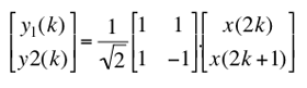
|
| |||||||||||||
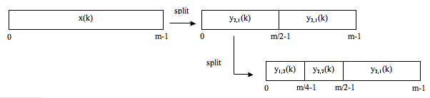
This transformation splits a discrete signal x(k) of size m into two parts y1(k) and y2(k) of size m/2. For splitting an image, the same decomposition is applied first on columns, then on rows. In this session, we assume that the image is square and that its size is a power of 2.
1.1 Analysis
The wavelet transform is implemented using 3 methods:
The methods analysis() and split() are already written. Your assignment is to code the method split_1D() in the file Code.java.
Test your work on mire.tif and aletsch.tif using the plugin Image Transform: check "Transform", uncheck "Processing" and "Inverse" and select n=3 in the dialog box. Select the output in "True Values" or in "Scaled Values" in which case the coefficients of the wavelet transform are rescaled between 0 to 255.
1.2 Synthesis filter and implementation
Write the synthesis filter in matrix form to reconstruct back the original signal x(k) form its sub-parts y1(k) and y2(k); fill in the report.
Your assignment is to code the three methods that perform the inverse wavelet transform.
Test your work on mire and aletsch.tif, check "Transform" and "Inverse", uncheck "Processing".
1.3 Check the transformation and reconstruction process
We propose to compare the reconstruction of 4 transformations on the image aletsch.tif
Compute the SNR between the original image and the reconstructed image (transform+inverse). Using the plugin SNR. Conclude and fill in the report.
2. Modifying sub-band wavelet coefficients
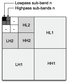 The wavelet coefficients are stored according to the arrangement shown on the right figure where n is the total number of scales.
Write the routines keepHighpassSubBand(coef, n) that only preserves coefficients of 3 highpass sub-bands (HLn, HHn, LHn) at level n and sets to 0 the other coefficients, and keepLowpassSubBand(coef, n) that only preserves the coefficients of the lowpass (LLn) sub-band at level n. Choose the "Keep 3 Highpass sub-band" or "Keep 1 Lowpass sub-band" as processing in the plugin.
Make the following experience on the aletsch.tif image:
Comment on the wavelet family and on the effect of the parameter n and fill in report.doc.
3. Comparison of the transform in term of compression
Simple data compression is achieved by applying a hard threshold to the coefficients of the wavelet transform (used in JPEG2000) or the DCT (used in JPEG). Note that this is only a rudimentary form of compression. A true coder would further quantize the wavelet coefficients which induces additional errors. The resulting coefficient map would also need to be encoded efficiently using, for example, the EZW algorithm (Embedded Zero-tree Wavelet coding).
To apply the compression function, check "Transform", "Processing" and "Inverse" , select "Hard threshold" and the rate (percentage of non-zero coefficients). If the rate is 10%, the image will be reconstructed using the 10% largest transform coefficients.
Compute the SNR between the original image (aletsch.tif) and the compressed image to assess the quality of the compression for the 3 transformations "Haar Wavelet, 6 scales", "Spline Wavelet, 6 scales" and "DCT 8x8" and for the rate = 2% and rate = 10%. Insert in the report the best obtained image for the rate = 2% and rate = 10% and fill in report.doc.
4. Detection of in-focus areas
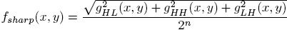
 We propose to design a simple detector of sharp (i.e in-focus) areas based on the wavelet transform.
The sharp areas are characterized by larger coefficients (high-energy)
in highpass sub-bands. The algorithm is the following:
We propose to design a simple detector of sharp (i.e in-focus) areas based on the wavelet transform.
The sharp areas are characterized by larger coefficients (high-energy)
in highpass sub-bands. The algorithm is the following:
4.1. Coding
Write the routine detectSharpArea() which implements the described algorithm. The parameters n and T are given through the dialog box.
4.2 Experimentation
Report the result of your experiences in the report.doc for the 3 images: roadrunner.tif, paper-text.tif and retina.tif.