| Biomedical Imaging Group |
| CONTENTS | ||||||||||
|---|---|---|---|---|---|---|---|---|---|---|
| Home Page | ||||||||||
| News & Events | ||||||||||
| Members | ||||||||||
| Publications | ||||||||||
| Tutorials and Reviews | ||||||||||
| Research | ||||||||||
| Demos | ||||||||||
| Download Algorithms | ||||||||||
| UnwarpJ | ||||||||||
|

| DOWNLOAD |
|---|
| UNIX distribution |
| Macintosh distribution |
| PC distribution |
UnwarpJ
An ImageJ plugin that performs a spline-based elastic registration of two images.
Carlos Óscar Sánchez Sorzano, Philippe Thévenaz, Michael Unser, Biomedical Imaging Group, Swiss Federal Institute of Technology Lausanne
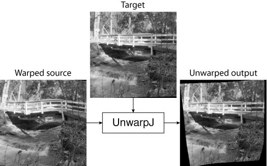
Figure 1. Deformed Bridge image (left), original bridge image (top), and a version obtained after elastic registration (right).
General Description
UnwarpJ is a plugin developed for ImageJ that allows the elastic registration of two images, by unwarping a source image so that it is made to resemble a target image. Three modes of operation are available: 1) a fully automatic mode; 2) a fully interactive mode where the deformation is uniquely determined by the position of any number of landmarks; 3) a mixed mode where interactive landmarks are used only to provide guidance to an otherwise automatic registration procedure. The deformation model is made of cubic splines, which ensures smoothness and versatility. The registration criterion includes a vector-spline regularization term to constrain the deformation to be physically realistic.
I. Download
This distribution is dated July 8, 2006. It includes the complete set of source files, along with the precompiled classes.
- UNIX distribution [491,520 bytes]
- Macintosh distribution [222,876 bytes]
- PC distribution [150,785 bytes]
II. Related Work
This Java class is based on the following paper:
C.Ó. Sánchez Sorzano, P. Thévenaz, M. Unser, "Elastic Registration of Biological Images Using Vector-Spline Regularization ," IEEE Transactions on Biomedical Engineering, vol. 52, no. 4, pp. 652-663, April 2005.
It is written as a plugin for ImageJ. Please read the ImageJ documentation to learn how to install the plugin.
III. Technical Explanations
This plugin allows you to register two images assuming that one of the images (source image, Is(x, y)) is an elastically deformed version of the other (target image, It(x, y)) such that
Is(g(x, y)) = It(x, y),
where g(x, y) is the deformation field. Elastic fields can be expressed in terms of B-splines as
g(x, y) = ∑k,l ck,l β3(x ⁄ sx − k) β3(y ⁄ sy − l).
B-spline-represented fields include all affine deformation fields (e.g=2E, translation, rotation, scaling, and more), and B-splines allow the representation of any regular deformation field with any desired accuracy simply by reducing the spacing and size of the B-spline.
Registering two images is equivalent to finding the ck,l coefficients that minimize the distance (energy Eimg) between the deformed source image and its target, given by
Eimg = (1 ⁄ #Ω) ∑x, y ∈ Ω (Is(g(x, y)) − It(x, y))2,
where Ω = {(x, y) ∈ Ωt: g(x, y) ∈ Ωs} is a mask defined with two other masks (one in the source image, and another one in the target image). To help the algorithm to find the desired solution, landmarks and regularization can be provided through the three other energy terms given by
Elandmarks = (1 ⁄ N) ∑n=1N ||μs(n) − μt(n)||2,
Ediv = ∑(x, y) ||grad(div(g(x, y)))||2,
Erot = ∑(x, y) ||grad(rot(g(x, y)))||2.
All these terms are linearly combined into the following single objective function that is minimized for ck,l:
E = wimg Eimg + wlandmarks Elandmarks + wdiv Ediv + wrot Erot.
IV. User Manual
Generalities
You need to open the two images to register in ImageJ. Then, you can call the UnwarpJ plugin. The following window will pop up:
Figure 1. Main menu.
Select in this menu the source and target images. The registration mode can be "Accurate" or "Fast" and it affects the stopping criteria internally used by the program. More internal options can be modified through the "Advanced Options" button.
If you want to exit the plugin, press "Cancel". When you want the plugin to perform the registration press "Done". Press "Credits…" to get information about the plugin. After running the plugin, normally the result is a stack with the following three images:
- The source image registered as to fit the target image;
- The target image;
- The source mask with the same deformation as the source image.
Showing the registered source image and the target image in the same stack has advantages since simply by changing quickly from one image to the other one can perceive the regions where the most important differences lay. (In the present example, differences remain in the resulting stack because we took care to build the source image from the target image in such a way that its exact recovery is impossible. A much better recovery can be observed if one changes the field "Final Deformation" in the "Advanced Option" panel from "Fine" to "Very Fine.") The registered source mask is useful for further processing of the source image. The following figure shows these three results for the images in Figure 1:
Figure 2. Left: Registered source image. Middle: Target image. Right: Registered source mask.
During the registration process, the current difference image and a mapping of the grid from the target image onto the source image are shown.
Figure 3. Left: Error image shown during the process. Right: Mapping of a grid from the target image to the source image, superimposed to the source image.
Toolbar
The toolbar will change to
Figure 4. Adding a landmark.
The depressed button indicates that you may ADD A LANDMARK now. Landmarks are added in either image. The landmark will be automatically placed in the same position on both images. The new landmark becomes the "current landmark" (indicated by a thicker [+] sign in the current image and a [×] sign in the other image, while all the rest are represented by [+] signs). To move any landmark, press on the MOVE LANDMARK button.
Figure 5. Moving a landmark.
Click and drag on any landmark to make it correspond to the same position in both images. Here goes an example of the two bridge images with corresponding landmarks.
Figure 6. Corresponding landmarks.
Landmarks can be removed through the REMOVE LANDMARK button.
Figure 7. Removing a landmark.
This program allows you to use masks in two mutually exclusive ways. In the first way, masks are introduced together with the input images. In this mode, input images must be a stack of images (first slice: the image itself, second slice: the mask). In this way, the mask can have any shape. In the second way, the input images must not be stacks and simple polygonal masks can be used. These masks are defined using the two buttons (INNER MASK and OUTER MASK) shown below:
Figure 8. Inner mask activated.
Figure 9. Outer mask activated.
The inner mask keeps the information in the interior of the polygon, while the outer mask keeps the information in the exterior of the polygon. The thrown-out information is grayed. Here goes an example of an inner mask:
Figure 10. Example of an inner mask.
Masks can be used for one of the images, both, or none. You can put a mask in one of the images and not in the other, you can put a mask (with different shapes) in both images, or you may not use masks at all.
Finally, the I/O MENU button allows you to perform several operations with the information of the program.
Figure 11. Button to access the I/O menu.
When you click on this button, the following window appears:
Figure 12. I/O menu.
The first two buttons are used to load and save sets of landmarks. A file dialog lets you choose the appropriate file. "Show landmarks" show the current landmarks in the following format:
Figure 13. Example of a trace of the current landmarks.
The first column is the index of the landmark. The other columns give the (x, y) position of the landmark in the source and the target images.
The "Load Transformation" option is used to reapply previously found elastic transformations (see "Advanced options" to learn how to save transformations).
During the registration process the toolbar will be changed to
Figure 14. Appearance of the window while registration is in progress.
Click on the stop button to stop the process. The output at the current state of the optimization will be returned in the normal way.
Advanced Options
When you click on the advanced options button of the general menu, the following window appears:
Figure 15. Advanced options.
This window gives you access to most of the internal parameters of the algorithm. The "Initial" and "Final" deformation lists allow you to select the coarsest and finest scale of the spline deformation field. "Very coarse" correspond to 4 splines (one in each corner of the image). As you increase the deformation level, the number of splines is doubled in each direction (horizontal and vertical).
The different weights of the goal function control the relative weight of each one of the terms. These weights are not restricted to be between 0 and 1, and they may take any value as long as it is non-negative=2E
The stop threshold is used by the algorithm to stop the optimization process at each multiresolution level when the error relative change is not larger than this threshold.
The verbose mode produces more information:
- The elastic deformation as a vector field. Each point in the target image must be deformed according to this field to fit into the source image;
- The grid obtained after deforming the target image after the vector field shown above;
- The values of the optimization process in a separate window.
Here are some examples of this information:
Figure 16. Left: Deformation as a vector field. Right: Deformed grid.
Figure 17. Values of the goal function f during the optimization process.
If you click on "Save transformation" the computed deformation is saved at the end of the process. All the B-spline coefficients, and relevant information to recover this deformation is saved in a file specified by the user through a File Dialog. Use "Load transformation" in the I/O menu of the Toolbar to read this transformation.
V. Macro and Command-Line Invocation
Calling the program as an ImageJ macro or from the shell command line might be useful in the automation of registration processes. UnwarpJ offers all its functionality in this mode, too. In this call mode, UnwarpJ performs three different operations:
- Help: Shows the syntax of the arguments to pass
- Align: Performs the alignment of two images
- Transform: Applies a previously computed transformation to a given image
For instance, to see the syntax of UnwarpJ as a macro you may run it as
run("UnwarpJ ","-help");
To call it from the shell command line, you must call the java interpreter providing the directory where ImageJ is, where the ImageJ plugins are, and where UnwarpJ is. A shortcut might be to create an alias that will do this for you each time you call UnwarpJ from the command line. To do this type in the shell prompt
alias UnwarpJ 'java -Xmx512m -Dplugins.dir=$IJDIR/ImageJ -cp $IJDIR/ij.jar:$IJDIR/plugins/UnwarpJ UnwarpJ_'
where $IJDIR is the directory where ImageJ is installed. In some Mac OS X machines the alias might have to be changed to
alias UnwarpJ 'java -Xmx512m -Dplugins.dir=$IJDIR/plugins -cp $IJDIR/ImageJ.app/Contents/Resources/Java/ij.jar:$IJDIR/plugins/UnwarpJ UnwarpJ_'
=46rom now on, you may call the plugin from the command line and build shell scripts to automate any registration process. For instance, to see the plugin help from the command line you only have to type in the shell console:
UnwarpJ -help
The syntax of the command line is exactly the same either it is run as a macro or from the shell. Thus, in the following we will explain them together for the three different modes: help, assign, and transform.
Help Mode
As already seen the syntax for getting help is
UnwarpJ -help
A help message with the syntax will be shown either in the shell terminal (if called from the shell) or in a separate window (if called as a macro). Several examples of use are given.
Alignment Mode
In this mode, the program aligns two images. The syntax is
-align <targetImage> <targetMask> <sourceImage> <sourceMask> <minScale> <maxScale> <DivergenceWeight> <CurlWeight> <ImageWeight> <OutputImage> [<LandmarkWeight> <LandmarkFilename>]
where the target and source images and masks can be any existing image filename that can be in any format readable by ImageJ. (If no masks are to be used, type "NULL" as name of the file.) <minScale> and <maxScale> stand for the deformation minimum and maximum scales (0 is the coarsest possible deformation). The typical <minScale> and the typical <maxScale> is 2. <DivergenceWeight> is the weight of the divergence regularization term, <CurlWeight> the weight of the curl regularization term, <ImageWeight> is the weight of the image term and <OutputImage> is the name of the output file (the registered source image) in TIFF format. Optionally, two more parameters might be given in order to provide landmarks. In that case, the weight of the landmarks and the landmarks themselves must be given. Landmarks are given in text file that can be generated by calling UnwarpJ as a normal plugin, clicking on the landmarks and saving them into a file using the corresponding menu button.
The transformation is always saved in a file called as the output file without the last extension to which "_transf.txt" is added. For instance, if the output file is called output.tif the transformation file will be called output_transf.txt.
The normal output of the plugin when run from ImageJ Plugin menu is 32 bits. However, this kind of images cannot be usually read by most imaging programs. For this reason, when the plugin is run from the command line or as a macro, it generates an output that is 16 bits which is much more commonly read.
Examples
For instance, to align two images without landmarks and without mask type
UnwarpJ -align target.jpg NULL source.jpg NULL 0 2 1 1 1 output.tif
To align two images with landmarks and mask
UnwarpJ -align target.tif targetMask.tif source.tif sourceMask.tif 0 2 1 1 1 1 landmarks.txt output.tif
Finally, to align two images using only landmarks
UnwarpJ -align target.jpg NULL source.jpg NULL 0 2 1 1 0 output.tif 1 landmarks.txt
Transform Mode
The transform mode allows applying the transformation computed with some source image to some other image. This is very useful in specific cases: for instance, the transformation might be computed in a denoised image and then applied to the original image. For doing so, you must first run the program in the alignment mode, get the transformation saved to a file (in the previous examples, output_transf.txt), and then call the program again with this transformation and the image to which you want to apply it. The syntax to apply a transformation is
-transform <targetImage> <sourceImage> <transformationFilename> <OutputImage>
The source image is the one to which the transformation will be applied. The target image is used to know the dimension of the output image and must be the same image that was used during the alignment step since the deformation is computed for its specific size.
Examples
For instance, to apply the transformation already computed in the examples of the alignment mode, you must type
UnwarpJ -transform target.jpg anotherSource.jpg output_transf.txt anotherOutput.tif
Producing JPEG images
The TIFF output of ImageJ may not be compatible with some image processing programs. For solving this problem when calling the plugin from the command line or as a macro you may force to produce a JPEG output with a 100% quality. For doing so, simply add "-jpg_output" as the last argument of the command line in the align or transform mode. For instance,
UnwarpJ -transform target.jpg anotherSource.jpg output_transf.txt anotherOutput.jpg -jpg_output

UnwarpJ -align target.jpg NULL source.jpg NULL 0 2 1 1 0 output.jpg 1 landmarks.txt
	-jpg_output
VI. Registering Color Images
UnwarpJ is prepared only to perform registration between gray images. However, the registration of color images can be easily done by converting the input color images into gray ones, then performing the registration and finally applying the transformation to each of the color channels of the input color images. To perform all these tasks you may benefit of the following algorithm and code:
- Open the two input images that you want to register in ImageJ.
- Convert them into gray images. You may do this manually (Image->Type->8-bit) or by the use of the macro UnwarpJColorPreprocessing.txt. This macro assumes that there are only two images open in ImageJ (the two that you want to register).
- Then, perform the registration making sure that you are saving the transformation (click on "Advanced Options" in the UnwarpJ menu).
- Finally, use another macro (UnwarpJColorPostprocessing.txt) to apply the calculated transformation to all channels in the source color image. This macro needs the names of the two input color windows (source and target) and the filename of the transformation. As in the following example
// Target and source images (Window name of the color images)


// Note that these are window names and not filenames


target="mandrill.jpg";


source="deformedMandrill.jpg";


// Filename of the transformation (full path)


// Make sure that the path does not contain any white space


transformation="C:\\SomeFolder\\grayOutput_transf.txt";
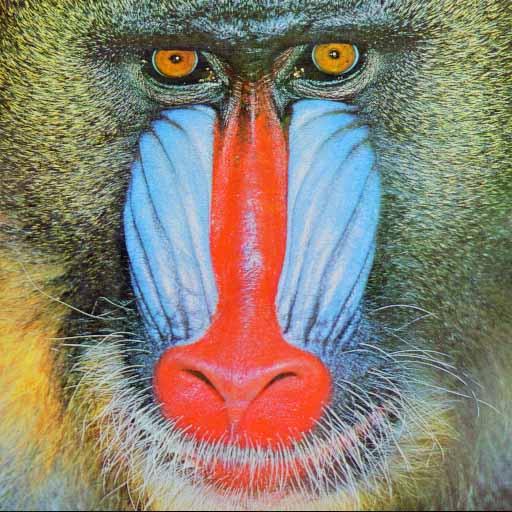
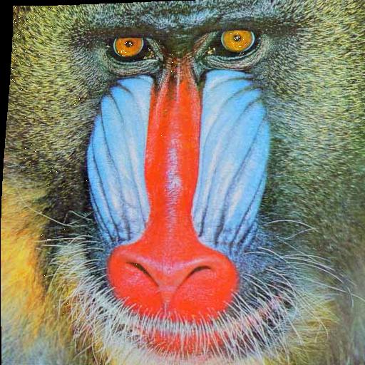
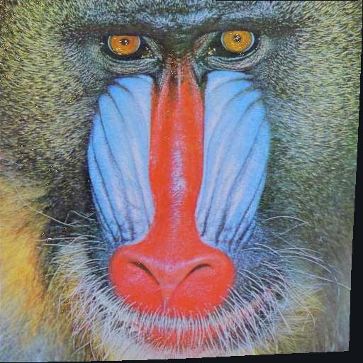
For this example we used a deformed version of the mandrill image supplied by ImageJ. The result is
| Target | Warped Source | Unwarped output |
|
|
|
VII. Conditions of Use
You'll be free to use this software for research purposes, but you should not redistribute it without our consent. In addition, we expect you to include a citation or acknowledgment whenever you present or publish results that are based on it.